Product

CRID

An automated polyhedral mesh generator for CFD. Import STL, describe what you want, export to your solver.

Automatic and efficient

Mesh generation that runs itself

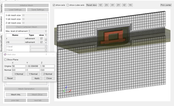
Set a base cell size, choose refinement levels per patch, and CRID does the rest: a Cartesian background grid is refined anisotropically, trimmed by the geometry into cut-cells, and finished with advancing-layer prisms at the walls.

  • Anisotropic refinement per axis
  • Cut-cell based trimmed hexahedral mesh
  • Boundary layers using the advancing-layer method
  • Curvature and feature-level refinement
CRID mesh-generation panel next to a refined Cartesian grid
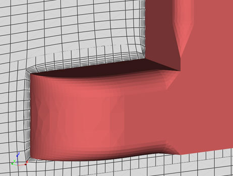
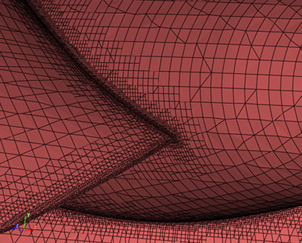
Close-up of trimmed hexahedral cells hugging a curved wall
Easy to use

Features by angle, or by a click

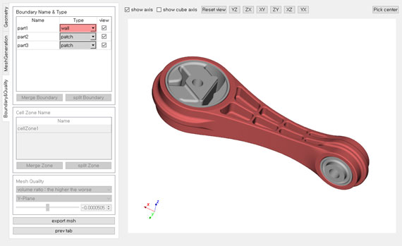
Sharp edges matter for mesh quality. CRID finds feature segments automatically from the dihedral angle, and lets you add or remove them by picking in the 3D view. Patches are merged or split along those segments without leaving the viewport.

  • Feature segments by angle threshold
  • Mouse picking in the 3D view
  • Merge selected patches in one action
  • Split a patch by feature segments
Connecting-rod geometry with patches listed in the CRID side panel
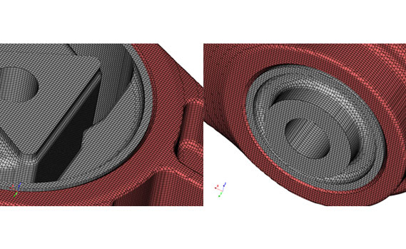
Mesh detail on the connecting-rod bore
Accurate geometry

The mesh follows the surface, not the other way round

Cut-cells keep the exact STL surface while the interior stays hexahedral. Feature-level refinement locks sharp edges in place, so trailing edges, blade tips and pipe junctions come out crisp.

  • Exact surface representation from STL
  • Feature-level refinement on edges
  • Consistent quality on blades, hulls and pipes
  • Mesh slice view to inspect the interior
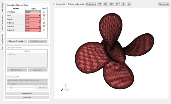
Five-blade propeller loaded in CRID
Boundary-layer mesh on a propeller blade edge
Workflow

Mesh generation with CRID

01

Set up geometry

Import STL, group surfaces into patches, transform if needed.

02

Identify feature segments

Detect sharp edges by angle or pick them with the mouse.

03

Establish patches

Merge selected patches or split them along feature segments.

04

Specify mesh conditions

Base cell size, per-patch refinement levels, boundary-layer settings.

05

Generate the mesh

Check, refine, cut and add layers, then export to your solver.

Import / Export

Import
Stereolithography (STL)
Export
OpenFOAM polyMesh with cellZones
ANSYS Fluent (.msh)
STL of the current geometry

Supported platforms

Windows
Windows 10 / 11 (x64)
Linux
Ubuntu 20.04 / 22.04
CentOS 7 / 8

Project and automation

Project file
.crd keeps geometry, settings, mesh and options together
Journal
Record a session to .jrn and replay it for repeat jobs and regression tests
Roadmap

Where CRID is heading

Performance
  • Parallelization
  • Optimized algorithms
Functionality
  • Interface patches
  • Batch execution
Platforms
  • macOS (Apple Silicon)
UI / UX
  • Advanced mesh visualization